Magnetic Flux and Flux Linkage - A Level Physics
An investigation of the effect on magnetic flux linkage of varying the angle using a search coil and oscilloscope.
Students must investigate how the induced emf in a coil varies with its angle relative to a magnetic field. The practical links induced emf and magnetic flux linkage. Students are assessed on correct assembly of the coil and oscilloscope and systematic variation of the angle. The investigation involves recording peak emf values in a table for different angles and plotting graphs to examine the angular dependence.
Subject: Physics | Level: A Level |
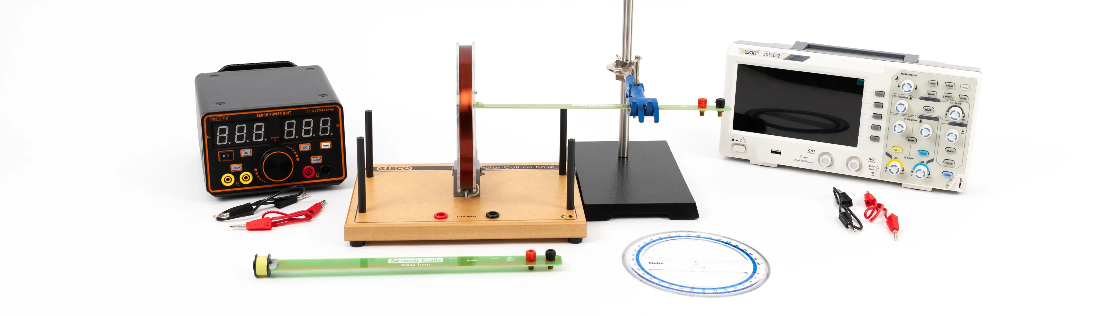
You will need:
Method
connect the circular coil to the AC power supply or AF signal generator and attach the search coil to the oscilloscope
The search coil is clamped so that the plane of the coil is initially parallel to the plane of the large circular coil, and therefore perpendicular to the B-field lines produced by the circular coil. This position will produce maximum flux linkage and maximum induced emf in the search coil.

Conducting the experiment
A preliminary experiment will be necessary to determine the appropriate voltage (and frequency) to use on the circular coil. (An ammeter might be required to ensure the current through the circular coil does not exceed the manufacturer’s specifications.)
Select suitable voltage sensitivity and time base settings on the oscilloscope, to establish that the induced emf produced in the search coil is large enough to be easily measured.
With the search coil in the initial position, record the induced emf in the search coil from the CRO display
Tilt the angle of the search coil and use a protractor to measure the angle between the plane of the circular coil and the plane of the search coil.
Measure the corresponding induced emf in the search coil from the CRO display
(It might be possible to clamp a large protractor behind the search coil support rod, although students could be set the task of devising a suitable method to measure this angle).
Repeat the experiment
Repeat for a range of angles from 0° to 90° between the search coil and the circular coil, and in each case measure the corresponding induced emf in the search coil.
Calculations and Analysis
Plot a graph to show the variation of induced emf against the angle of the search coil in the field. This should be maximum for the position shown in the diagram, where the angle between the plane of the circular coil and the plane of the search coil is 0°. The induced emf should be zero when the plane of the search coil is at an angle of 90° to the plane of the circular coil.
Technician tips
A large circular coil of approximately 15–20 cm diameter is connected to an AC supply. The search coil can be positioned to investigate the magnetic field at the centre of the circular coil.
An oscilloscope connected to the search coil can be used to measure the induced emf, which is proportional to the magnetic field strength and flux linkage in the search coil. By tilting the search coil at different angles to the field, the variation of flux linkage with angle can be investigated.
The circular coil can be placed flat (horizontal) on a suitable surface or mounted vertically with a stand. If you have a pair of circular coils used as Helmholtz coils, one of these could be used together with the dedicated stand which supports the coils vertically. Do not exceed the specified current rating for the coil or damage will result.
Alternatively a circular coil can be made by wrapping about 10 turns of 0.45 mm PVC covered copper wire into a coil of about 15 cm diameter. This can be placed flat on the bench. A 50 Hz AC current of about 5 A will usually provide a sufficiently strong field at the centre of this coil. (This is similar to the arrangement suggested in the Nuffield Advanced physics course.)
Either an axially or laterally mounted search coil can be used. The search coil can be clamped at the centre of the large circular coil. The induced emf in the search coil can be measured on the oscilloscope.
If the induced voltage is not large enough to measure on the oscilloscope, an AF signal generator can be used with the circular coil instead of the 50 Hz AC supply. The higher frequency will give a greater induced emf in the search coil. (Typically a frequency of 5–10 kHz might be used, but some preliminary experimentation is required to find what works best with your circular coil and search coil).
Use a ‘protractor card’ under a circular coil to measure the angle between coil and search coil.
Use blu tack and optical pins to point the centre of the circular coil for consistent readings when rotating the search coil.
For better precision reading of the angle, use 3D printed arrangement.
use 3D printed arrangement.
360° Protractor card


