Determination of g by Freefall method - A Level Physics
Students must determine the acceleration due to free fall. The practical links measured distances and times to acceleration. Students are assessed on accurate timing and measurement of drop heights. The investigation involves recording times for different heights in a table and plotting results to determine the value of g.
Subject: Physics | Level: A Level |
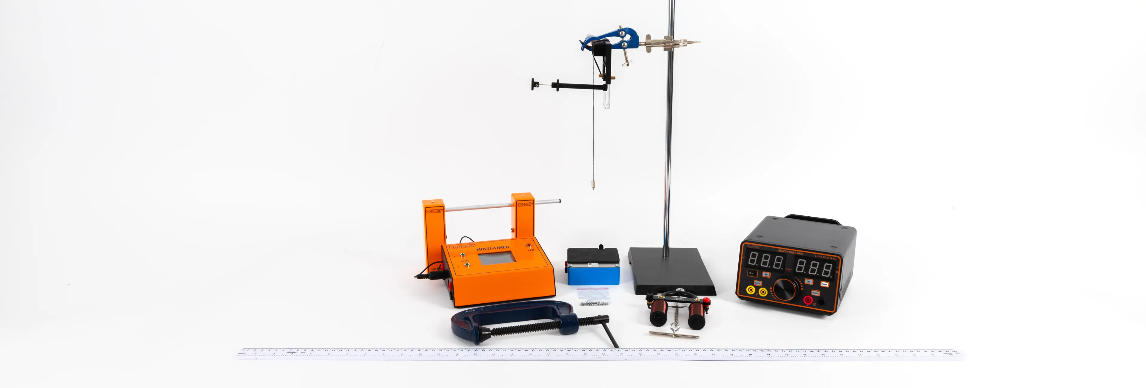
You will need:
• Plumbline
Method
Preparation and setup
Place the retort stand on the bench with the base facing away from where the pad/ sand tray will be. Place the 2kg mass on the retort stand bass.
Clamp the electromagnet to the top of the retort stand (opposite to the base)
Clamp the upper light gate under the electromagnet
Clamp the lower light gate to the retort stand– adjust to ensure the ball bearing will trigger the light gates (a plumbline could be used)
Connect the DC supply to the electromagnet
Connect the light gates to the data logger or electronic clock
Place the pad or sand tray underneath the light gates.

Conducting the Experiment
The height between the starting position of the ball bearing and the upper light gate should be kept constant, so that the velocity, u, with which the ball bearing reaches this light gate is also constant.
Adjust the position of the lower light gate so that h is 0.500 m measured using the metre ruler (If a taller stand is available, h could be set at a higher starting value).
Switch on the supply to the electromagnet and hang the ball bearing from it (or fit the ball bearing into the clamp if a mechanical release mechanism is being used).
Reset the clock or data logger to zero and switch off the electromagnet (or open the clamp).
Read the time on the clock or data logger once the ball bearing has passed through the light gates.
Take repeat readings to find the mean time, t.
Repeat the experiment
Reduce h by 0.050 m and repeat the procedure down to a value of 0.250 m (lower values than this make it difficult to obtain accurate timings).
Calculations and Analysis
Plot a graph of 2_h_/t against t.
Draw the best straight line of fit though the points and find the gradient (the graph should be a straight line with intercept 2_u_).
h = ut + gt2/2
Re-arranging
2_h/t_ = gt + 2_u_
Hence the gradient of the graph gives g in ms–2
The intercept will be 2_u_.
Technician tips
The electromagnet is a convenient way of releasing the ball bearing.
The low voltage supply should be set at the voltage specified by the manufacturer for the electromagnet.
The supply is switched on and the ball bearing hung from the electromagnet. It will then be released when the supply is switched off.
Several trials and adjustments will be required to ensure the ball bearing falls directly through the light gates. A plumb line can be used to make sure that the ball bearing will fall through both light gates and hit the pad.
A sand tray can be used instead of the pad.
A mechanical release mechanism could be used (eg holding the ball bearing in the clamp which is opened to release the ball bearing, but this is not as quick to reset and won’t give as clean a release).
The upper light gate should be connected to the clock or data logger to start the timing.
The lower gate should be connected to stop the timing.
The 2 kg mass is used as a counterweight to ensure the stand does not topple over (an alternative would be to clamp the stand to the bench using a G-clamp).


