Magnetic Flux Density - A Level Physics
An investigation of the relationship between magnetic flux density, current and length of wire using a top pan balance.
Students must investigate the force on a current-carrying wire in a magnetic field. The practical links force, current, and wire length. Students are assessed on measuring force accurately and controlling current and wire length. The investigation involves recording force for different currents and lengths in a table and plotting graphs to explore the relationships.
Subject: Physics | Level: A Level |
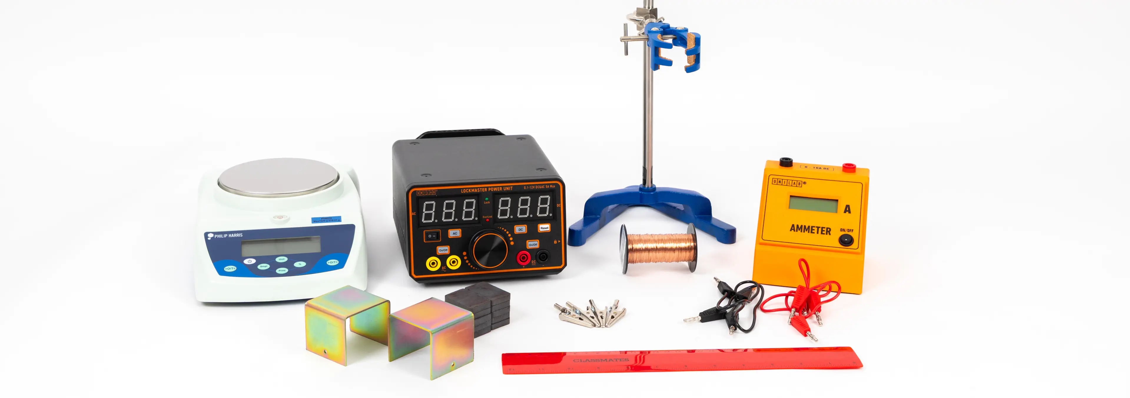
You will need:
Method
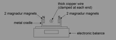
Preparation and setup
Place a stack of 2 magnadur magnets at the top of both inner sides of the metal cradle
Place the cradle onto the centre of an electronic balance
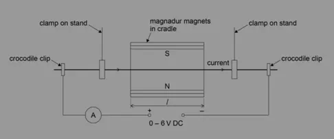
Clamp the thick copper wire at each end and position it inside the cradle in line with the magnets
Create a parallel circuit with the wire alongside the power supply and ammeter.
Conducting the experiment
With no current flowing through the wire, set the electronic balance to zero.
Adjust the voltage of the supply so that the current, I, flowing through the wire measures at 6.0 A on the ammeter.
Read the top pan balance display, m, in grams.
Repeat the procedure for I = 5.0, 4.0, 3.0, 2.0 and 1.0 A.
Repeat the experiment
Obtain a second set of results by repeating the experiment and find the mean value of m for each value of I.
Calculations and Analysis
Plot a graph of the mean m against I.
Draw the best straight line of fit though the points and find the gradient (the graph should be a straight line through the origin).
Measure the length of the magnadur magnets, L, in metres. (This will be the length of wire in the magnetic field, ignoring edge effects)
The force on the wire is:
F = BIL (where B is the magnetic flux density in Tesla)
F = mg/1000 (converting m into kg and with g = 9.81 Nkg–1)
Equating
BIL = mg/1000Re-arranging
B = mg/(I × L × 1000)The gradient of the graph gives m/I
Hence B = gradient × g/(L ×1000)The value obtained for B is typically around 5 × 10⁻² Tesla
Technician tips
High currents (up to 6 A) will flow through the wire, so care must be taken as it will get warm.
The current and field directions will give an upward force on the wire according to Fleming’s left hand rule. However, because the wire is clamped and cannot move, there will be a downward force acting on the magnets and cradle which will cause the reading on the electronic balance to increase.
Add a rheostat (11Ω works fine) in series to vary current
Rotate the magnadur magnets by 90º to obtain more data with different wire length, L.


