Young's slit experiment and diffraction - A Level Physics
Students must investigate interference and diffraction using light and diffraction grating. This practical links fringe spacing to the wavelength of light. Students are assessed on correct alignment of optical components and accurate measurement of fringe patterns. The investigation involves recording fringe separations in a table and plotting graphs to calculate or compare wavelengths.
Subject: Physics | Level: A Level |
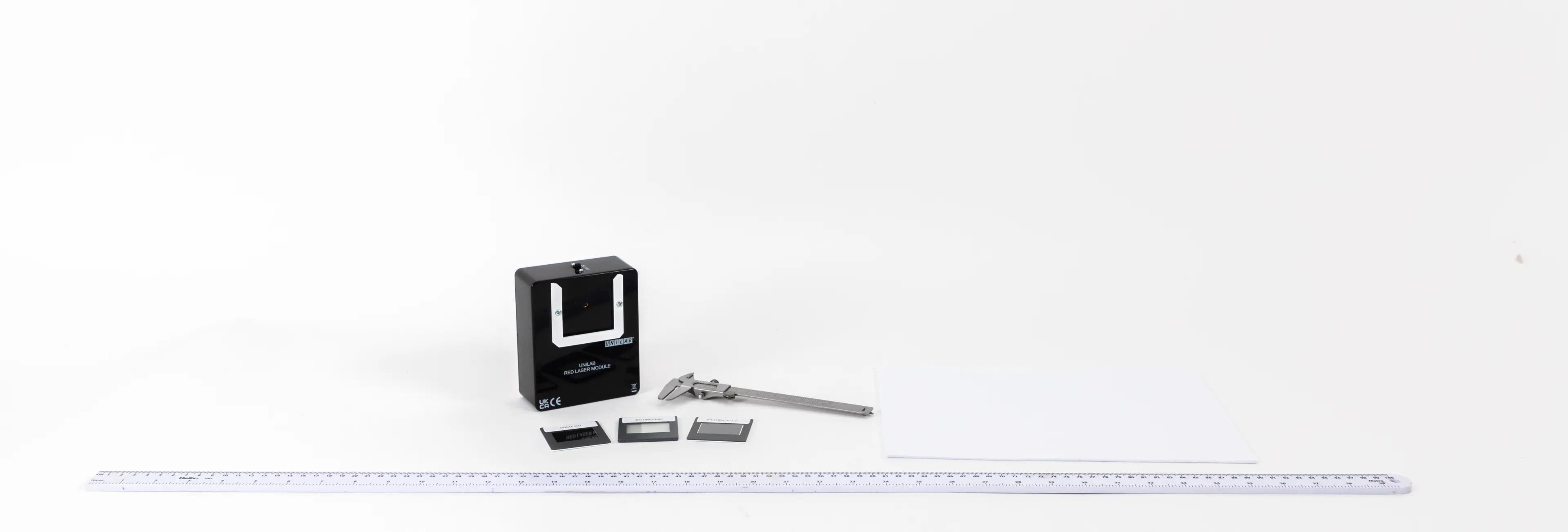
You will need:
• White screen (or wall covered with matt white paper)
• Metre ruler
Method
Preparation and setup
A partially darkened laboratory is required ensuring lasers are used safely.
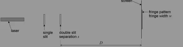
Set up the apparatus by fixing the laser and the slits to a retort stand and place the screen so that the distance from the double slit to the screen is 0.5 m (D), measured using the metre ruler
Darken the room and turn on the laser
Conducting the experiment
Carefully adjust the position of the laser until the light spreads evenly over the two slits. An interference pattern should be visible on the screen.
Measure from the central fringe across many fringes using the vernier callipers and divide by the number of fringe widths to find the fringe width, w
Repeat the experiment?
Increase the distance D by 0.1 m and repeat the procedure, increasing it by 0.1 m each time up to around 1.5 m
Repeat the experiment twice more and calculate and record the mean fringe width w for each distance D
Calculations and analysis
The fringe width (or fringe spacing), w, can be measured by measuring across a large number of visible fringes. (Take care when counting – counting from the first bright fringe to the tenth bright fringe would represent nine fringe widths!).
Use the metre ruler to measure D.
A measurement of the slit separation, s, is required. The value could be measured with vernier callipers or travelling microscope. If a travelling microscope is used it must only be used to measure slit separation and not the fringe width. Alternatively the manufacturer may quote the value on the slide.
Use the equation λ= w s / D
Alternatively, the value of D could be changed from approximately 0.5 m to 1.5 m and the fringe width, w, measured for each value of D.
A graph of w on the y-axis against D should be a straight line through the origin, with gradient = λ /s.
Method - Diffraction grating
Preparation and setup
Swap out the single slit with the plane transmission diffraction grating.
Conducting the experiment
Carefully adjust the position of the diffraction grating so that the diffraction grating is perpendicular to the beam of light from the laser. (A large set square might be useful).
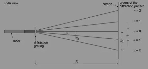
The diffraction pattern should be visible on the screen. The number of orders shown will depend on the line spacing of the diffraction grating.
Repeat the experiment?
Use a set square to ensure the beam passes through the grating at normal incidence and meets the screen perpendicularly
Set the distance D between the grating and the screen to be 1.0 m using a metre ruler
Darken the room and turn on the laser
Identify the zero-order maximum (the central beam)
Measure the distance h to the two nearest first-order maxima (i.e. n = 1, n = 2) using a vernier calliper
Calculate the mean of these two values
Measure distance h for increasing orders
Repeat with a diffraction grating that has a different number of slits per mm
Calculations and Analysis
The angles Ɵ1 and Ɵ2 can be determined by measuring the distances h1, h2 and D. (This gives the tangent of the angles, and hence the angles can be calculated).
The formula nλ = d sinƟ can be used to determine the wavelength of the laser light.
n is the order of the diffraction pattern
d is the grating spacing = 1/number of lines per metre
λ is the wavelength of lightThe values of Ɵ for each order, both above and below the zero order, should be measured. A mean value for λ can be calculated from the data.
Technician tips
Using a laser for this experiment makes it possible to produce visible interference fringes in a partially darkened laboratory.
Ensure lasers are used safely and set up so they are not pointed directly into anyone’s eyes. Remove reflective surfaces from the room to ensure no laser light is reflected into anyone’s eyes.
Single slit diffraction - This arrangement can also be used to illustrate diffraction at a single slit. The diffraction grating is replaced by an adjustable single slit. The effect of ‘slit width’ can easily be observed.
Ensure the use of the set square to avoid parallax error in the measurement of the fringe width


