Investigating the charge and discharge of capacitors - A Level Physics
Students must investigate charging and discharging of capacitors in RC circuits. The practical links voltage, current, and time for transient circuits. Students are assessed on correct circuit construction and accurate timing or voltage measurements. The investigation involves recording voltage over time in a table and plotting graphs to determine the time constant and examine circuit behaviour.
Subject: Physics | Level: A Level |
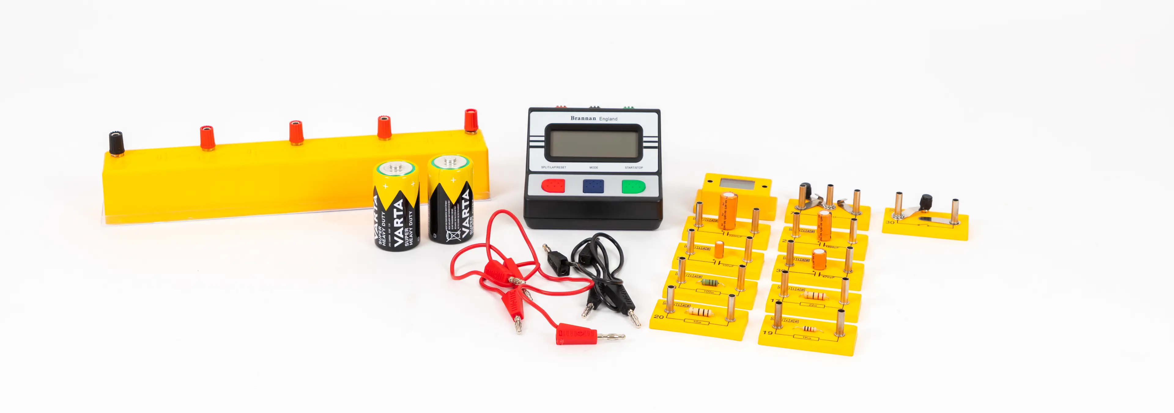
You will need:
Method
Preparation and setup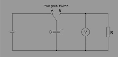
Discharging a capacitor through a resistor
With the two pole switch in position A the capacitor will charge.
Move the switch to position B so that the capacitor, C, will discharge through the resistor, R.
Move the switch to position A to charge up the capacitor.
Switch to position B, start the stopwatch, and observe and record the voltage reading at time t = 0.
Continue to take voltage readings at 5 s intervals as the capacitor discharges. (For a slower discharge, voltage readings at 10 s intervals will be sufficient).
Charging a capacitor through a resistor
Close the switch to start the charging process
Observe and record the voltage across the capacitor at 5s intervals (or longer time intervals if the charging process is ‘slow’).
Repeat the experiment
Charging and Discharging a capacitor through a resistor
Repeat the process with the same capacitor and different resistors.
The process can also be repeated with different capacitors.
Ensure the capacitor is completely discharged before starting each new charging process
Calculations and Analysis
Discharging a capacitor through a resistor
Plot a graph of pd across the capacitor, V, on the y-axis against time, t. This should give an exponential decay curve, as given by the equation V = V0e –t/RC
To confirm that this is an exponential, plot a graph of Ln(V/V) on the y-axis against t. This will give a straight line graph with a negative gradient according to the ‘log form’ of the equation
ln(V) = ln(V0) - t/RC
This graph will have a gradient of
Hence, the time constant RC can be determined from the gradient of the graph. If R is known, the value of C can also be found
Charging a capacitor through a resistor
Plot graphs of pd, V, on the y-axis against time, t. The graph will show an ‘exponential growth’ of pd across the capacitor as it charges as given by the equation.
V = V0(1-e –t/RC)
Technician tips
It is essential that the electrolytic capacitors are connected into the circuit with correct polarity, as indicated on the capacitor body.
The voltage rating of the capacitor should also be greater than the dc supply used.
Resistor and capacitor values listed, have been chosen to give a time constant RC in the range 10 s to 500 s.
The internal resistance of the battery is usually enough to limit the charging current to a safe value,but allowing the capacitor to charge up almost instantly.
It is well worth doing a ‘trial discharge’ to see how quick the discharge is so that a suitable time interval can be decided when taking voltage readings during the discharge process.


